To control household electrical lighting sources, various devices are used, the most common among all is a switch. This is a simple device located on the wall and connected to wires. The design of the products is different, but the internal circuit diagram for single models is the same.
In our material we will tell you how to connect a switch with one key to quickly make repairs. For convenience, several connection methods with thematic photographs will be shown that clearly demonstrate the installation process.
Design and purpose of circuit breakers
A switch is a simple mechanical (rarely electronic) device for contact closure / opening of an electrical circuit in order to turn on / off lighting devices.
We will cover design features and installation of the simplest models - single-key switches.
They consist of 4 main parts:
- work node - metal base with contacts and push-button drive;
- fasteners - metal legs or antennae connected to a metal plate;
- decoration - panels or frames;
- dynamic part - plastic keys.
Part of the parts, mainly internal, is made of metal, for example, galvanized steel, the external decorative finish is usually made of safe plastic. Ceramic elements that can withstand loads up to 32 A are possible, while plastic is designed for 16 A.
Among the reasons for installing a one-button switch are:
Image Gallery
Photo from
Single lamp wall light
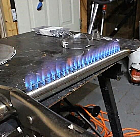
LED line or fluorescent lamp
LED Ceiling Light
Damaged circuit breaker
The external and internal structure depends on several factors, for example, functional tasks or potential load. As an additional device, in some models there is an LED that provides external illumination.

The design of a simple switch with one key: 1 - the key with which the mechanism is put into action; 2 - decorative frame; 3 - the working part, which is enclosed by an electrical mechanism
Switches are installed in all rooms where there are any lighting devices that are not equipped with a power cable (for example, for floor lamps or table lamps it is not needed).
These are most often ceiling or wall lamps, chandeliers, complex lighting systems.

When choosing devices for rooms with a high level of humidity, you should pay attention to such an indicator as the level of protection: IP 20 is enough for a bedroom or living room, IP 40 for a bathroom or kitchen, IP 55 for outdoor (street) installation
Types of devices for domestic use
There is no strict division into categories, as different manufacturers have their own, “branded” lineups, however, several types of circuit breakers can be distinguished, united by any one sign.

The two most common types of modern switches are a single-key wall model and a control panel, which is usually supplied with a light fixture
For example, according to the principle of inclusion, all devices can be divided into:
- mechanical - elementary keyboard devices, easy to install and use (the function of a key can be performed by a lever, a toggle switch, a button, a cord, a rotary knob);
- electronic touchdriven by the touch of a hand;
- with remote controlequipped with a remote control or motion sensor.
The first group is considered to be the most demanded, traditional and recognized from the first days of the invention of the electric circuit, the popularity of the third is also gaining momentum, and the second somehow did not take root.
Motion sensors save energy and provide additional protection. For example, if you install a similar device at the entrance to the house, it will signal the appearance of uninvited guests.

In residential premises, it is preferable to install internal models (with or without backlight) that do not protrude above the wall surface and look more aesthetically pleasing
By design type, all switches are divided into single-key and multi-key (standard version for domestic use - with 2-3 keys). Each key serves to close / open one lighting circuit.
If there are several lighting devices in the room - a chandelier, ceiling lights and sconces - a three-key switch is appropriate, which will allow to turn on / off the devices alternately or together.
Also quite popular are the two-key switches that can be seen in almost every apartment. They are especially relevant for chandeliers with several lamps.
According to the installation method, two groups can be distinguished: with external and internal installation. Outdoor type usually used when wiring is open, and interior - with cables sewn into the wall. To ensure the safety and stability of the installation of the built-in switch, use the mounting box (socket) - a protective plastic case.

According to the installation method, the switches are divided into built-in and overhead. The former are used for closed wiring, the latter for open wiring. Both options are installed according to similar schemes.
Placement - Convenience and Security
Before installing the switch, you should consider the most convenient place for installation and subsequent use. The most advantageous area is located near the entrance doors (from the side of the door handle), but there may be exceptions (for example, near the head of the bed).
Before drawing up a wiring project, it is better to look at the official document - Electrical Installation Code (Electrical Installation Rules), which governs some of the nuances of installation. For example, paragraph 7.1.48 states that the switch must be at least 60 cm from the shower, and paragraph 7.1.50 allows it to be installed no closer than 50 cm from the gas pipeline.

As can be seen from the installation diagram, the distance from the doors to the installation point should be at least 10 cm, and to the floor at least 90 cm
In bathrooms and saunas, the installation of control devices is prohibited, they must be taken outside the premises (usually in the corridor).
Three mounting options for single-key switches
Consider three switch connection schemes that are similar in design (have one key), but differ in the type of installation. Also, all options are united by the basic law of the introduction of single-key models: a dynamic element opens the "phase", and not "zero". In the opposite case, there is a risk of injury during repair work and even with a simple lamp replacement.
# 1: Photo instruction for installing an outdoor device
The location of the wires for this connection scheme does not matter: they can go on the surface or inside the wall. The outdoor type of switch in the living room is welcome if an expensive repair has just been made and there is no desire to re-tear down the walls and conduct the channels.

The simplest connection scheme for a single-key switch, which serves as the basis for the practical actions of novice electricians: wire L (phase) goes to the switch, the rest - directly to the light source
We will consider the option with external cable laying, in which the wires are enclosed in a corrugated protective channel.

At the installation site of the switch, the corrugated pipe fixed on the wall with special clips is cut reproach, and the working insulated wire is pulled out
Under the switch, there will be another electrical device - a socket, so the cables for both devices for aesthetic reasons are enclosed in one corrugation.

The power cable associated with the outlet will pass through the patch switch so as not to make a loop and increase the installation area
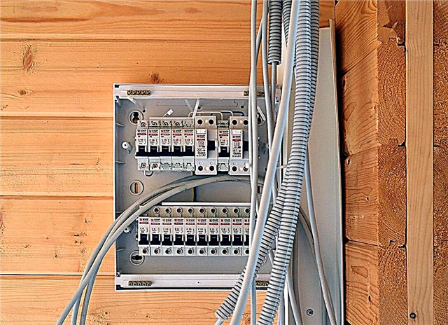
Selected Circuit Breaker Model - Schneider electric - has a plastic case and degree of protection ip44. Before installation, we take safety measures: turn off the power to the cable on the electrical panel installed on the site or in the corridor.
Use an indicator screwdriver to verify that there is no voltage in the cable. When the issue of power outage is resolved, we take up the disassembly of the switch.
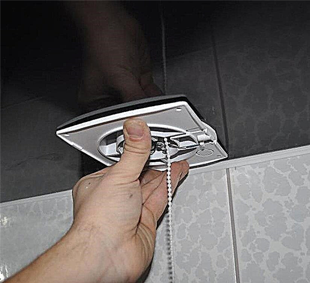
First we take out the key with our hand - this is done quite easily.

Under the button that closes the switch on top, there is another plastic protective strip - the front panel, which also needs to be removed by gently pressing the holders
The next step is the removal of the working mechanism.

The mechanism that makes the circuit / opening of the electric circuit is not fixed with special holders or springs, so it gets quickly and without problems
Now you need to accurately determine the installation location of the switch and mark the points on the wall for screwing fasteners. To do this, we take an empty housing and apply it to the wall.
We level it, with a marker we designate points for drilling. Using a drill, we drill holes for fasteners (another method of fastening is also possible).

We fix the plastic case in a designated place on the wall using dowels - the best option for fixing on concrete and brick substrates
From the switch housing, remove the elastic plug located in the upper part, insert it into the wire hole and the end of the corrugated pipe coming from the ceiling.

The result should be a neat tight connection of the corrugation with the body with free access to wires for further work
Time to proceed directly to the connection. From the ends of the wires we remove the insulating material, we clean 8-10 mm.
We connect the white wire (phase) to the terminal with the designation L, blue - to the other terminal, with the designation "1". Carefully tighten the bolts and place the working unit in the housing.

The wire leading to the outlet is laid in the bypass of the working unit and displayed in the lower hole of the housing, there we insert the second end of the corrugated pipe
We reassemble the switch: put the front panel in place, then fix the key.

At the end of the work, we test: turn on the power supply and press the button several times. If the light comes on when turned on, the connection is correct.
Do-it-yourself installation of the switch is quite easy, even if installation is complicated by the presence of additional devices.
However, if you are not sure about the correctness of the actions, it is better to be safe and conduct the first connection under the supervision of an experienced electrician.
# 2: Workshop on replacing an old switch
Often, in connection with repairs in an apartment or a private house, you have to dismantle the old switch and install a new, more modern and convenient one in its place.
Consider the basic steps for replacing a circuit breaker using step-by-step photographs of the process.

Before us is an old unsightly model of a built-in switch installed inside the concrete base of a panel house. It is necessary to remove it by unscrewing the two fixing bolts
Using a screwdriver, unscrew the screws, remove the plastic cover.

Under the cover is an old connection mechanism in which the cores are fixed with a bolted connection. Bolts are visible on the left, metal fixing "ears" on both sides
Our task is to determine the "phase".

To find the working wire, we use a voltage indicator, which usually acts as an indicator screwdriver with a light signal
Alternately, we bring the screwdriver to the contacts, in no case touching them with our hands (it is better to use insulating gloves). For an accurate definition, set the key in both positions.
With the off position, the "phase" supplies only one contact. The second wire is for the lighting fixture.
Having established the purpose of the wires, we turn off the electricity supply, check the presence or absence of voltage, and making sure of safety, we begin to disassemble the old switch. We unscrew the fasteners of the metal holders (“paws”), we get the working unit.

Carefully disconnect and isolate the wires: first the "phase", then the second wire. For insulation, it is better to use electrical tape of different colors, so as not to make a mistake when connecting
We finally release the mechanism, straighten the wires - the place for the new switch is prepared. We take a new product, purchased in advance, and prepare it for installation, in other words, disassemble.
We remove the key, unscrew the protective panel and see the internal mechanism - with two required clamps and spacer holders.

The screws located at the edges regulate the movement of the “paws”, and those located on top serve to connect the wires - they are used to adjust the contact pressure plate
We clean the ends of the wires by about 1 cm, insert them into the holes located under the upper screws, and make sure that the winding does not slip in along with the bare wire. Tighten tight so that the wires do not move.

If the holes are marked, insert the "phase" into the hole marked "L", the lead-out wire is "1". Instead of the indicated designations there can be the numbers “1” and “2” - then the “phase” will go to “1”
After connecting the wires, we insert the working unit into the mounting box.

To prevent the mechanism from “walking” inside the socket, we fix it with metal holders, tightening the side fixing screws
Set the top panel, fix the key.

We test the operation of the device, although it is better to perform the first test before the internal mechanism is completely fixed - so that you do not have to redo it
So, to install a new switch, we needed tools (screwdriver, pliers, knife, wire cutters, indicator screwdriver), some insulating material and 20 minutes of time. Calling an electrician would cost about 500 rubles.
# 3: Connection diagram with junction box
When bare walls get, which is found in new modern model houses, you have to independently insert interior doors, floor, tidy the walls.
Wiring is no exception. Therefore, we will consider how to properly connect the circuit breaker together with a lighting fixture, circuit breaker and junction box.

You need to start by choosing a connection scheme. In the figure - the simplest one, with one light source, a single-button switch and access to the panel, we complicate its installation of automation
Our goal is to install all the devices in designated areas for them and connect them together with wires, without confusing them. We try to install the junction box in the center.
The open or closed method of cable installation does not fundamentally affect the arrangement of circuit elements.

As a result of the preliminary installation, the following scheme should be obtained: automatic block + junction box + mounting box for the switch + exit to the lamp + three-core cable with a cross section of 1.5
First of all, we connect an automatic protection device that protects the network from overloads and power surges.
Decide on the color of the wires that we need to connect the switch:
- white - phase;
- blue - zero;
- yellow - land.
We clean the wires and insert them into the terminals intended for them. We use the yellow wire for grounding, fixing it separately with a special clamp.

Three-wire wire is considered universal. To connect the luminaire, a two-wire one would be enough, however, it is better to predict events and, just in case, prepare wiring for connecting 2 devices or a chandelier
The role of the lamp will be played by an ordinary cartridge and a light bulb (incandescent, LED, energy-saving).

We clean the wires and connect them to the cartridge, inserting them into the holes intended for this. The yellow wire is gently bent and insulated
We bring the wires into the installation box to install the switch.

When connecting the switch, the yellow wire is also not useful. We clean the other two, isolate the yellow and bend to the side
Modern models of switches have marked terminals, which facilitates the fixation of wiring. We insert them into the desired holes and fasten with screws.

After connecting the wires to the switch mechanism, insert the working unit into the mounting box, put the case on top, fix the key
All elements of the circuit are connected, it remains to connect the wires in the junction box.

Remove the insulation, strip the ends of the wires, twist them first with your hands, then with pliers. We make the connection according to the colors according to the picture, uneven tips are removed with wire cutters
We check the correctness of the connections with an indicator screwdriver and test it - press the switch button.

If the lamp lights up and goes out under the control of the switch, all steps are performed correctly. Turning off the power, hide the wires and close the junction box
As you can see, the entire connection scheme can be performed independently using a minimum of simple tools.
Useful video instructions will help novice electricians learn the theory and put it into practice correctly.
Instructions from the manufacturer legrand which will discuss how to install the switch yourself:
From the following video you can find out about connecting a single-key switch and an outlet:
As you can see, the principles of connecting various electrical devices are similar, but have slight differences. Having decided to replace the circuit breaker yourself or lay the entire circuit, carefully study the schemes, consult qualified specialists, and be sure to observe safety precautions in the process.
If you still have questions about replacing single-key switches or have additions to the material, please leave your comment in the block below.