In the cold season, the need for heat is increasing. But not every owner has the opportunity to purchase a factory-made heater. There is nothing complicated in assembling a heater with your own hands.
We bring to your attention four options for creating a heating device from improvised means, which will perfectly cope with the task assigned to it. We described in detail the process of making homemade products. They described the principle of operation and operation features.
To the walkthroughs we have attached diagrams, photo selections and video instructions.
Devices for local heating
The simplest models of home-made heaters are designed for local heating. Their maximum heating temperature is about 40 ° C.
For the most part, home-made heating relate to radiating devices operating on the principle of infrared heaters and electric radiators. They are connected to a single-phase network with 220 V, which is traditional for household objects. Those who want to do the independent manufacture of devices need knowledge in the field of electrical engineering and wiring.
Image Gallery
Photo from
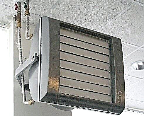
Homemade heat gun
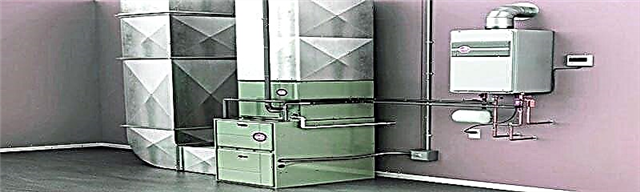
Water heater model
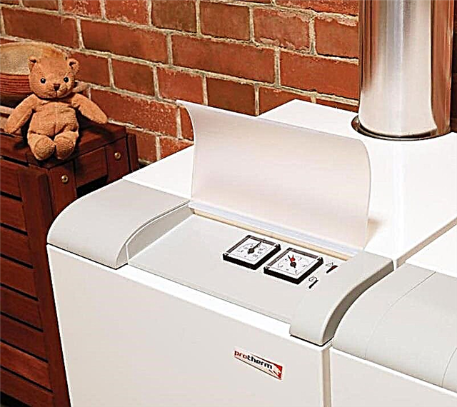
Option induction miniature device
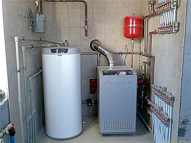
Garage Heating Unit
Option 1. Homemade compact thermal film
The basis of the heater will be two glass cuts. These are the same rectangles 4x6 cm in size.
The length and width of the heater’s working area may vary. The main thing is that the area of each glass is about 25 square centimeters.
To create such a home-made heater, you will also need:
- copper two-wire cable;
- multimeter;
- paraffin candle;
- wooden block;
- pliers;
- sealant; epoxy adhesive;
- cotton napkin;
- hygienic sticks.
Before starting work, the cable must be equipped with a plug.

The heating element will be a piece of aluminum foil used by the hostesses for baking, the thickness of which is 0.1 mm
First of all, the glass blanks are cleaned, removing dust and dirt with a napkin, degreased and thoroughly dried. The cleaned workpieces are cooled. This is necessary so that during subsequent firing, the carbon deposit settles better on the surface.
Set the candle set in the candlestick. And then they alternately grab each glass blank with pliers by the corner and carefully move them above the candle so that the glass is covered with soot. It is necessary to achieve uniform sedimentation of soot on the entire surface of the glass; burnt part and will act as a conductive element.
Manipulations with a candle will have to be interrupted periodically in order to allow the heated glass to cool slightly.

The main advantage of such a device is that a significant part of the thermal energy is released by the material heated up to a certain temperature in the form of infrared radiation
After cooling the blanks, each of them cleans the edges. To do this, with the help of hygienic sticks along the contour around the perimeter, 5 millimeters from the edge are removed.
On the burnt part, which will act as a conductive element, glue is uniformly applied, on top of which a previously prepared piece of foil is applied. The strips will serve as the terminals needed to connect the wires.
The same actions are performed with the second half. Both parts connect. To ensure the tightness of the device, the joints are treated with a sealant, covering the end along the entire perimeter.

To make heating elements, two strips are cut out of foil, the width of which corresponds to the size of the smoked area on glass blanks
In order to calculate the power of the device, it is necessary using a tester to measure the resistance of the carbon coating. The multimeter probes are applied to the hanging “tails” of aluminum foil. The data obtained are used in the calculation using the formula:
N = i2 x R
where "N"- power,"I"Is the current strength, and"R"- resistance.
Power should not exceed permissible values of 1.2 watts. If the resistance exceeds a value of 120 OM, to reduce it, it is necessary to make the carbon layer a little thicker. Here the following rule applies: the more soot, the lower the electrical resistance.
If the parameters are within the normal range, they proceed to the final stage of assembly. To do this, the stripped edges of the preforms are lubricated with glue, and the free ends of the foil sections are bent and glued to one of the sides.

A stand is made of a wooden block and pads connected to the electric cord are mounted on it
A structure assembled from glass and foil is installed on a wooden platform and the device is connected to a 12-volt source.
Option # 2. The heating panel from the remains of the IR floor
If film fragments remain after the heating infrared floor device, they should be safely put into the business of manufacturing a wall heater, for example, for a summer house or garage.

Their scraps of infrared film remaining after the device of the heated floor in the house, you can build a wall panel, and if you want to decorate it with a laminated large-sized photograph
Infrared film consumes less energy than other heating electrical devices. For a small room of approximately 2 × 2 m, 1 m of carbon film system is sufficient.
Image Gallery
Photo from
Step 1: In order not to be distracted in the process of work, you need to stock up on everything you need in advance. Consumables require a foil substrate under the IR floor, directly film, 0.75 wire, a temperature controller or a socket with a timer and bitumen tape
Step 2: Cut the infrared film according to the required dimensions. We cut only in transparent strips, it is impossible to cross the carbon strips at an angle or cut across
Step 3: The available clamp to which the wire will be connected has a larger diameter. In order to tightly clamp it, it is necessary to carry out preparatory measures
Step 4: The wire stripped from insulation by about 10 - 15 cm is bent in half, then again and everything is twisted into a bundle and crimped with pliers
Step 5: Tightly twisted, sealed with pliers wire set in the clamp
Step 6: Connect the clip with the wire to the edge of the current-carrying copper film element, disconnecting the edge of the polymer transparent shell from its rear side
Step 7: The lower part of the clamp is inserted into the space between the disconnected polymer film and the copper conductor
Step 8: Cooking the bitumen tape. It is used to isolate all electrical connections and cuts of the copper conductor from the side opposite to the connection
Preparation of materials and tools
Cutting infrared film to size
Preparing the wire for connection to the system
Thickening for connecting the clamp
Installing the wire harness into the clamp
Connecting an electrical wire to the system
The specifics of connecting the wire to the film
Bitumen tape for insulation
Now you need to carefully insulate everything so that the film does not spark on the contacts and does not create any threats in the process of its own work.
Image Gallery
Photo from
Preparing adhesive tape segments for gluing
Clamp and wire insulation
The process of gluing electrical connections
Rules for gluing bitumen tape
Insulation of the second strip
Fixing on foil backing
Trimming excess around the perimeter of the system
Socket with timer instead of thermostat
Option # 3. Available fan heater
We offer another affordable method of manufacturing a home-made device for local heating, which is based on the principle of operation of a fan heater. Its manufacture will take no more than two hours. The main advantage of such a device is the simplicity of manufacture and the availability of the necessary materials.
Among the design flaws is the fact that during heating it will burn oxygen, and in some cases even smell like burning.

The body of the device will be made of a tin can with a height of 20 cm with a diameter of 10 cm, and the strips for winding a spiral of nichrome will be made of non-folded textolite
In addition to the can for assembling the heating structure, it is necessary to prepare:
- 12 volt transformer;
- diode bridge;
- 1 mm nichrome wire2;
- fan;
- punch with a thin drill;
- soldering iron;
- computer fan.
Two blanks must be cut out of the PCB in advance, the size of which corresponds to the dimensions of the selected can. To connect the device to the network and switch modes, you will also need an electric cord and a button switch.
First of all, the foil is removed from the cut of the PCB and the inner part is cut out so that it looks like a frame.

In a textolite billet, holes are drilled using a thin drill, placing them with a slight offset relative to each other
The ends of the nichrome wire are deepened into the holes made. To the free ends of the wire brought under the frame, the “tails” of the electrical wires are cleaned from insulation.
The current density in nichrome spirals in contact with air is about 12-18A / mm2. Depending on the degree of heating, their color saturation will vary from maroon to bright red. The temperature of the outer surface of the emitter does not exceed 70 degrees.

They take a transformer, a diode bridge and a cooler and close them with a fixed nichrome wire into a single circuit, not forgetting to connect the switch
A diode rectifier and a small 12 V transformer are needed to power the cooler.
To be able to adjust the temperature, it is worth considering the option of installing at least two separated spirals. In addition, by connecting the spirals in parallel, if one burns out, the others will not suffer.
The main thing when assembling the structure is that the wound spirals do not touch any parts other than the textolite frame.
The fan is mounted in a jar using a bracket in the form of a U-shaped metal part fixed by a bolt. The current will warm the coils of wire, and the fan will blow the structure with a warm stream of air.

Textolite is attached to the assembled structure, after which the elements of the electrical device connected into a single circuit are placed in a jar
To ensure free air access in the lid and walls of the cans, 20-30 holes are drilled with a diameter of 1.5-2 mm. The assembled device is directly connected directly to a 220V network and its performance is checked. For safety reasons, the radiating surface can be covered with a protective net.
Such a fan heater is suitable for heating a small room. Like industrial models of fan heaters, it only warms up the middle of the room in just a few minutes, without wasting precious heat on the heat loss that goes through the walls.
Image Gallery
Photo from
The principle of operation of fan heaters
Ventilation part from the player
Homemade hairdryer
Those who wish to independently make a garage heater from improvised means will find a lot of useful information in another popular article on our site.
Home-made low-power devices
The models described above are only suitable for local heating. To heat a room, it is necessary to build a more powerful heater, the manufacturing technology of which we will consider below.
Option 1. Creating an oil device
A self-made oil heater has high efficiency and is also quite functional and safe. The principle of operation of the device is based on the fact that the heater located inside the heater warms up the oil located near it, as a result of which the convection movement of flows is activated.

The body of the product can be made from a sectional battery of the heating system, a car radiator, or welded from steel pipes
To ensure smooth power settings, the device is equipped with a rheostat or discrete switches. To automate the process, an additional thermostat and tilt sensor are installed.
To make an oil heater you need to prepare in advance:
- TEN with a power of 1 kW (for premises with an area of 10 squares);
- strong and tight case, the design of which completely eliminates leakage of liquid;
- clean and heat-resistant technical oil is taken at the rate of 85% of the total body volume;
- control and automation devices - are selected in accordance with the total power load of the device.
An important point when acquiring a cartridge tent, do not forget to check that silicone gaskets or their analogues made of oil-and-gas-resistant rubber are included in the kit.
In order not to mess with welding, a dismantled heating register can be used as a housing, dismantled due to the modernization of the public building system.
An impressive construction will require the construction of a platform. It can be made of channels or steel corners. When drawing up the scheme, the frames are repelled from the capacity of the tank and the height of the product.

The device connection diagram and the assembly sequence of its structural elements are graphically presented in the figure.
Complexity can arise at the stage of welding elements. After all, to complete the work you need to have the appropriate skills. The first step is to cut the profile pipe into segments of a given length. Rectangular frames are assembled from them.
A hole is cut out in the corner of the structure for the placement of the heating element. A hole is cut out at the highest point of the radiator to allow oil to be poured and equipped with a male thread fitting, on top of which a cover is installed.

Before putting the heater into operation, it must be tested for leaks, creating a lot of pressure in the middle of the device
When assembling the structure, attention should be paid to a number of points:
- It is better to place the heater in the side or lower part of the structure, fixing it with bolted connections. This solution will provide better oil circulation. Under no circumstances should it come into contact with the housing.
- To activate the process of natural convection of fluid, supplement the design with a pump and electric drive. To fix the pump to the tank, you need to weld small metal plates.
- Be sure to provide valve-mounted openings for emergency pressure relief by draining the oil. The pumps are located at the bottom of the radiator in the corners.
- To ensure the durability of the structure, preventing the development of electrocorrosion, consider the compatibility of the body metal and the heater. Due to the potential difference between metals, it is not worth combining ordinary steel or aluminum with copper.
- Ground the heater without fail.
The design is not completely filled with oil, but only by 85%. This is necessary so that 15% diverted into the air is a buffer zone during oil expansion due to temperature increase.
Image Gallery
Photo from
Cast iron battery as heater housing
Application of the heating system register
The use of a bimetallic radiator
Welded steel pipe construction
After checking the tightness of the holes, it remains only to connect the heater, install the housing and fill in the oil. To increase the mobility of the structure, it can be equipped with wheels and additional fastening elements.
Option # 2. Making an infrared device
The indisputable advantage of such a device is that the generated thermal energy is released in the form of infrared radiation. Thanks to this, a heater created on the basis of a carbon element warms up not only air, but also people and objects located in the infrared zone.
The basis of such a device, created by the type of factory-made heaters, will be two plastic billets, the area of each of which is about 1 square. Fine-grain graphite powder will be applied on them, in structure somewhat resembling flour.

Keep in mind that graphite powder, which acts as a conductive mixture, is an extremely dirty substance, and besides, it is very dangerous for health
To make an efficiently working IR heater with your own hands, you must also prepare:
- two copper terminals;
- epoxy adhesive;
- wooden blanks for the frame.
As in previous versions, you will need an electric cord equipped with a plug.
Graphite powder can be “mined” from old batteries. To obtain the required heater power, experienced craftsmen recommend introducing up to two volumes of carbon filler. In the finished form, a thick and viscous mixture is obtained, which is rather difficult to apply with a thin film. To simplify the task, use a narrow spatula.

The graphite composition diluted with glue is laid out on plastic blanks, making a winding path, not forgetting to retreat the allotted distance
The sequence of actions:
- Graphite is mixed with epoxy glue in a ratio of 1: 1.5 or 1: 2.
- On the work surface, lay the plastic blank with the smooth side down.
- The finished mixture is laid out in a thin layer on the plastic, forming a zigzag pattern.
- On top of the laid out pattern is a second sheet of plastic.
- Using the same technology, a second plate is prepared. Both blanks are tightly compressed and wait until the adhesive composition hardens.
- On the blanks on opposite sides of the graphite conductor, the terminals are fixed, adhering to the above diagram.
- The stripped ends of the electric cable are connected to the terminals.
- Connect the device to the network and check the performance of the system.
The measurement of the resistance of the conductor and calculation of the power of the assembled device is carried out, adhering to the technology described above.
The resistance parameter is affected by the amount of graphite in the mass. To increase the resistance of the conductor, you need to increase the dose of graphite in the composition.
To increase the rigidity of the structure, the device can be framed with a wooden frame. To improve the design, supplement it with a simple thermostat.
Video # 1. Overview of the spiral heater manufacturing option:
Video # 2. Homemade 1kW infrared heater:
We considered only a few options for manufacturing heaters from improvised means. In fact, there are a great many of them. If you wish, you can independently develop and manufacture such a device. And the reward will be the desired warmth in inclement weather.
Want to offer your own version of the heater? Have questions or is there any useful information for us and site visitors? Please leave comments in the block below.