Agree: the extra devices, without which the lighting system could well work, buy and install to anything. Such devices of doubt include the choke for fluorescent lamps. You do not know whether it is needed in the connection diagram or can you do without it?
We will help you deal with the issue. The article details the features, the purpose of the throttle and the functions it performs. The photo and wiring diagram are presented, which will help to independently assemble the fluorescent lamp and start it by correctly connecting all the components to the electrical circuit.
To help the home foreman, we selected a number of videos containing recommendations on connecting fluorescent bulbs, as well as choosing the right choke, depending on the type of lamp.
Purpose and device of a throttle
Discharge lamps, of which the luminescent variety is representative, cannot be ignited as usual, providing power supply. They simply will not work. To get a glow of this type of source, you will need to additionally use a ballasts.
The purpose of the ballast in the circuit
It turns out that for the functioning of a fluorescent lamp, it is necessary not only to ensure the flow of current, but also to apply voltage to it.
Therefore, the inclusion circuit uses ballast - resistance. It turns on in series with the lamp and is intended to limit the current flowing through its electrodes.
Its role can be performed by various electrical components:
- in the case of direct current, these are resistors;
- with a variable, a choke, a capacitor and a resistor.
Among these devices, the throttle is the most successful option. It has reactance without generating excessive heat. It is able to limit the current, preventing its avalanche-like growth when turned on in the mains.
Image Gallery
Photo from
Inductor in switching power circuits
High Frequency Limiter
Sectional winding wire
The throttle is not only an integral element in the starter switching circuit, it performs the following functions:
- contributes to the creation of a safe and sufficient current for a particular light bulb, which ensures the rapid heating of its electrodes during ignition;
- an increased voltage pulse generated in the winding contributes to the appearance of a discharge in the luminescent bulb;
- provides stabilization of the discharge at the nominal value of electric current;
- contributes to the trouble-free operation of the bulb in spite of voltage fluctuations that periodically occur in the network.
An important factor for the functioning of luminescent light sources is the inductance of the inductor. Therefore, when buying this electromechanical component, you should pay attention to the technical parameters that must correspond to the characteristics of the bulb.

When choosing an electromechanical ballast, which is also called a choke or current limiter, not only technical parameters, but also the reputation of the manufacturer matter - unknown Chinese companies can offer a limiter whose real characteristics are much lower than those stated
What does the ballast consist of?
The inductor used in the switching circuits of fluorescent type bulbs is nothing but the winding of a wire on the core - an inductor. It is its industrial design that bears the name of the throttle in electrical engineering, which literally translates as "limiter".

Different types of windings with a variety of cores, differing in size, shape and appearance. The inductance of a particular product directly depends on the thickness of the wire, the density of the arrangement of turns in the winder and their number, core shape and other parameters
A choke with the necessary technical characteristics is produced in an industrial environment, so the consumer will not have problems when choosing the right option that matches the parameters of the connected light bulb.
Moreover, having the skills to collect various electrical devices, the corresponding components and power tools, you can try to independently build a coil with the desired inductance.

In the diagrams, the image of the throttle may differ. In the circuits for connecting fluorescent bulbs, most often you can find option L6 - a winding with a magnetic core ferrite core
The throttle consists of the following elements:
- wire in insulating material;
- core - most often ferrite type or from other material;
- casting mass, compound - it contains substances that are resistant to burning, which provides additional insulation of the turns of the winding wire;
- bodyin which the winding is placed - it is made from heat-resistant polymers.
The presence of the latter element depends on the features and characteristics of a particular current limiter model.

Participating in the scheme of ignition of a discharge bulb together with a starter, inductive resistance in the form of a choke limits the current strength at the moment of voltage supply to the lamp, and the generation of self-induction EMF in the amount of 1000 V ensures its ignition and stabilizes arc burning
The starter circuit is imperfect, although it shows an excellent result. But the flickering of the bulb, the noise of the throttle and its large size, as well as a false start due to an unreliable starter, led to the invention of a more advanced version of the ballast controller - electronic.
Electronic ballasts in the process of functioning contribute to a reduction in power losses of up to 50%, relieve from blinking bulbs. Their use allowed to reduce the mass of chokes, as well as significantly increase the return of the lighting device.
True, the cost of electronic ballast is significantly higher than EMPR, and you need to purchase it from manufacturers with an excellent reputation - such as Philips, Osram, Tridonic, and others.
Scheme + self-connect
You just can’t turn on the fluorescent light - it needs an ignitor and a current limiter. In miniature models, the manufacturer prudently built all these elements into the housing and the consumer can only screw the product into a suitable lamp / chandelier holder and click the switch.
And for larger products, ballasting equipment is required, which can be either electromechanical or electronic type. To connect it correctly, ensuring trouble-free operation of the device, you have to know the procedure for connecting individual elements to the electrical circuit.

Connection diagram of a fluorescent light bulb (EL) using a choke device, where LL is the choke, SV is the starter, C1, C2 are capacitors
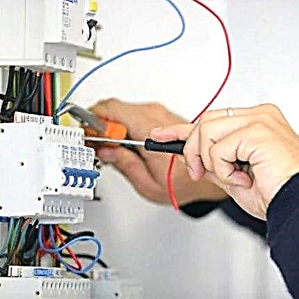
True, having a scheme, but not having practical experience in performing this kind of work, it will be difficult to cope with the task. Moreover, if the connection is required to be made outside the home - in the corridor of an educational institution or other public institution - then unauthorized interference in the operation of the electricity network can turn into problems.
To do this, the staff of the institutions must have an electrician working on an ongoing basis or serving the institution as the need arises for its services.

The scheme implements the connection of two fluorescent bulbs in series. A significant problem - if one of them breaks / burns out, then the second will not work either
Consider the step-by-step connection of two tubular LL to the power supply using the starter circuit. Why do you need 2 starters, a throttling component, the type of which must necessarily correspond to the type of bulbs.
And also you should pay attention to the total power of the starters, which should not exceed this parameter for the inductor.
Image Gallery
Photo from
Installation of bulb holders
Installation of lamps in holders
Connecting short wiring to starter holder
Checking the health of the assembled circuit
Connection long cable starter holder with LL
The second end of the core from the starter is attached to the second lamp holder
Connection of the first lamp with the second in one circuit
Power cable connection
When connecting the power cable to the lamp, it is important to remember that the inductor is responsible for limiting the current.
So, the phase core will have to be connected through it, and the neutral wire should be connected to the bulb.
Image Gallery
Photo from
The second core from the power cable should be inserted into the connector of the electromechanical ballast, which is also called the inductor. The correct hole is selected based on the designations printed on its body
Now we have to deal with the further formation of the chain, connecting the second LL with the second starter, and more precisely, with its holder. To do this, take another short core and insert one end into the socket of the bulb holder, and the other into the starter mounting hole
A similar procedure has to be done on the other side of the tubular luminescent, also using a short wiring. Particular attention should be paid to the reliability of the created contact - so that nothing hangs
It remains to complete the formation of the circuit using another long strand, the end of which is to be connected to the free socket of the holder of the second bulb, and the second to the hole of the throttle component
Now you need to fix all the elements of the circuit required for the operation of the assembled system. To do this, take 2 starters purchased in advance. It is important that their type and power match the LL parameters
Each starter, which is also called the starter, should be put in pre-prepared holders, to which they have already managed to connect the wires. This element is a small flask with two electrodes - a rigid and flexible bimetal
The second starter is similarly mounted in the cavity of the holder located on the opposite side next to the throttle. 2 light bulbs can be supplied from one 36 W ballast component
The most interesting thing remained - to check the assembled circuit in action by connecting the power cable to the electrical network. If everything is done correctly, then two LLs will start and begin to shine. Otherwise, they will not react in any way.
The phase core of the power cable is connected to the inductor
Connection of the second lamp to the second starter
Connection to the circuit of the second side of the lamp
Connection of a second lamp with a choke
One starter for each bulb
Installation of starters in holders
Throttle one on two bulbs
Checking the health of the assembled circuit
A similar connection scheme is relevant for large lighting fixtures. As for the compact models, they are equipped with a built-in trigger and adjustment mechanism - a miniature electronic ballast mounted inside the product.

In a compact fluorescent light bulb between the base and the tubes with a mixture of gases is a small ballast. It copes with the launch of the device and can significantly outperform other LL elements in terms of service life.
Throttle overheating and possible consequences
The use of light bulbs that have reached the end of their service life and occasionally cause various breakdowns can result in a fire. How to dispose of used fluorescent devices is described in detail here.
To avoid the occurrence of a fire hazard situation will help regular inspection of the condition of the lighting fixtures - visual inspection, verification of the main components.

By the end of the lamp service, you can notice a significant overheating of the ballasts - of course, you can not check the temperature with water, for this you should use measuring instruments. Heating can reach 135 degrees and above, which is fraught with sad consequences
If used improperly, a mercury bulb bulb may explode. The smallest particles are able to scatter within a radius of three meters. Moreover, they retain their incendiary abilities, even falling from the height of the ceiling to the floor.
The danger is overheating of the inductor winding - the apparatus consists of various types of materials, each of which has its own characteristics. For example, manufacturers impregnate insulating gaskets with complex compositions, some elements of which have varying flammability and smoke formation.

Even the seven turns of the throttle in which a short circuit occurred can become fire hazardous. Although the closure of at least 78 turns is a high probability of fire, this fact was established experimentally
In addition to overheating of the throttling element, there are other situations with fluorescent lamps, representing a fire hazard.
It can be:
- problems caused by a violation of ballast manufacturing technology, which affected the final quality of the apparatus;
- poor material of the diffuser of the lighting device;
- ignition circuit - with or without a starter, the fire hazard is the same.
It should be remembered that carelessness when making a connection, poor quality of contacts or circuit components, which most often occurs when using very cheap devices purchased from unknown manufacturers, can lead to problems.
Conscientious companies give a guarantee on their products, and the technical parameters of the devices indicated on the case or packaging are true. This fact directly affects the service life of both the ballast itself and gas discharge lamps, the features of the device and the operation of which will be introduced by the article recommended by us.
The subtleties of assembling a circuit of two LL with sequential inclusion:
Video about what a throttle is and why it is needed:
Checking the throttle for damage:
About the rules for choosing a throttle depending on the type of discharge lamp:
Having familiarized yourself with the purpose and arrangement of the chokes used to start the fluorescent bulbs, you can arm yourself with a connection circuit and try to implement it yourself. True, this is true for the home..
In public institutions, the solution of such issues should be entrusted to electricians with special access to electrical work.
Please write comments in the block below, post a photo on the topic of the article, ask questions. Tell us about how you selected and connected the throttle. Share useful information on aspects of device selection and installation technology.