Water-type underfloor heating is becoming more and more popular with owners of private houses heated from a boiler. The combined system, equipped according to all the rules, has been working properly for 15-20 years. A well-chosen scheme for connecting a water heat-insulated floor (ECP) provides a coolant supply, heating it to the desired temperature and distribution along the contours.
In this article, we will analyze in detail the features of the collector assembly and the system connection diagram. We also give detailed installation instructions. But first, consider when the water floor becomes useful, and when it is impractical to arrange it.
Restrictions for mounting an ECP
Manufacturers of components for underfloor heating (TP) do not always specify whether there are restrictions for installing water systems, but they exist. In some cases, it is forbidden to install heating structures.
Where it is not customary to install water floors:
- In multi-apartment buildings. Central heating is distributed between the apartments. An additional connection in one of them will lead to heating and hydraulic imbalance.
- In public places. Underfloor heating is considered to be ineffective, since heat losses are large, and essentially economical systems become expensive during operation.
- In residential buildings with insufficient thermal insulation as the main source of heat. One of the conditions for installing underfloor heating in the northern regions is to reduce heat loss due to insulation of walls and floors, as well as installing radiators around the perimeter of the premises, under the windows.
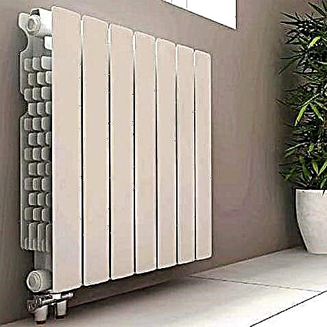
The combination of traditional radiator heating with underfloor heating is recognized as the most effective heating system, and heating batteries remain the main sources of heat.
But sometimes the system, hidden under the floor, plays a major role:
Image Gallery
Photo from
Spacious rooms with panoramic windows
Children's and game rooms
Warm floors, equipped in compliance with standards and technological nuances, are safe, hygienic and do not affect the aesthetics of the premises.
And for the functionality and ease of use meets the selected connection scheme, the description of which will dwell in more detail.
Analysis of the connection diagram with the collector
There are several options for designing a water TP system. But the most practical and rational design is recognized as a collector - a multifunctional unit that distributes the coolant.
The principle of heating
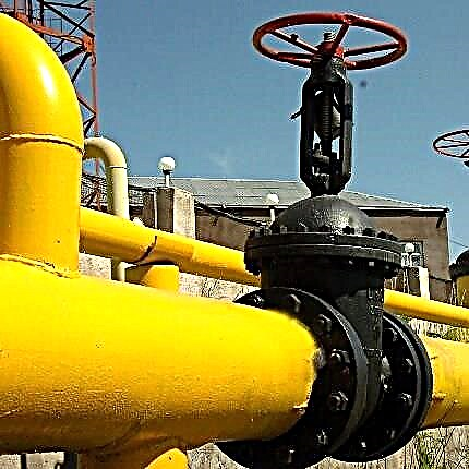
The main source of heat supply in the house, as a rule, is an autonomous generator, the function of which is usually performed by the boiler. The type of boiler does not matter, but it is estimated that gas costs 6-7 times cheaper than electric.

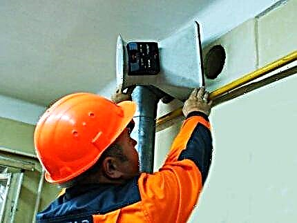
The boiler can be installed in the kitchen, corridor, basement or in a specially allocated room - a boiler room. Communication with radiators and underfloor heating is carried out by means of pipes (polypropylene, metal-plastic, etc.)
The temperature of heating water for heating reaches 95 ° C. The system is closed and the return temperature is lower - approximately 65-70 ° С. But for a warm floor, these parameters are not suitable, the maximum allowable value is 55 ° C. In practice, the coolant enters the ECP pipes even more cooled - 35-45 ° С.
In order to adjust the desired temperature, a return line is connected to the circuits and a mixing unit is installed, which mixes the flows.

Connection diagram: 1 - three-way valve; 2 - circulation pump type; 3 - ball valves with temperature sensors; 4 - collector for the distribution of coolant with flow meters; 5 - a collector with adjustment valves mounted on the return; 6 - warm floor "snail"
The temperature in the system can be adjusted manually, focusing on the data of temperature sensors. However, there are gas boilers designed for direct connection of the ECP. They automatically supply water with a pre-set temperature of 40-45 ° C.
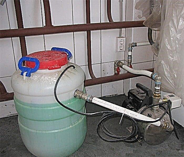
Solid fuel boilers are difficult to regulate. For the coolant in the system with a solid-fuel generator to reach the norm, the installation of an additional buffer tank is required.
But electric boilers are ideal, since the desired temperature is maintained in automatic mode, but this is the most expensive heating method, not economically viable.
Selection and assembly of the collector assembly
ECP circuits are connected to the heating system through a distribution manifold. This is a unit that allows you to adjust the flow of the coolant, control the temperature and flow, balance the circuits, and remove air from the system. For each function, individual elements are responsible: pump, flow meters, pressure gauge, thermostats.

Sample collector connection method. A comb is fixed to the wall, to which supply and return lines are connected on one side, and water circuits from one or several rooms on the other
In order to choose the right components for the assembly of the mixing-manifold assembly, it is better to hire a specialist who is well versed in the quality of parts on the market.
The main elements of the node:
Image Gallery
Photo from
On the supply line there is a manifold with balancing valves equipped with flow meters, on the outlet there is a similar manifold, but with ordinary valves or thermostatic valves
On both collectors, cranes are installed that perform 2 functions: removal of the coolant from the system and air discharge during the initial or next filling of the circuits with water
In the absence of a separate riser, a mixing unit is required, including a bypass, a thermostat and a pump. There are many options for installing the unit, depending on the location of the collector, the number of connected circuits and other installation conditions
There are several reasons for airing the system, so the installation of an automatic air vent is necessary. It is mounted on the side, preferably at the highest point of the collector-mixing unit, on the feed comb
Manifold combs with flow meters and valves
Drainage taps for emergency coolant drain
Mixing unit for coolant adjustment
Automatic air vent for air exhaust from pipes
In addition to the listed components, fittings (axial, compression or press fittings), special brackets are needed. The entire assembly is usually placed in a manifold cabinet, which may have a different design and installation location.
Step-by-step installation instructions
The water floor is connected to the heating system at the final stage, when the construction work is fully completed, the collector cabinet is assembled and installed.
The whole process of installing the VTP system includes the following steps:
- Design, calculations, charting.
- Preparation of the base, installation of insulation;
- Proper installation and fastening of pipes reinforcing mesh;
- Filling the circuits with coolant, hydraulic tests.
- Filling screeds, laying the finish flooring.
- Connection to the system, balancing circuits.
- Commissioning, testing.
As you can see, the connection activities are carried out at the very end. And here the contour balancing plays an important role. Each loop has a different length, respectively, all circuits differ in hydraulic resistance.
Instructions for connecting pipes:
Image Gallery
Photo from
Step 1 - put on protective tubes
Step 2 - install the clamping connection under the euro cone on the pipe
Step 3 - attach the fitting to the manifold fitting
Step 4 - gently tighten the connection
Step 5 - we plan the installation of the second end of the pipe
Step 6 - find the corresponding fitting on the back comb
Step 7 - adjust the position of the insulating sleeves
Step 8 - connect all the pipes in turn
If you install the collector assembly without flow meters, the heating function will be impaired. When the system is put into operation, the coolant will tend to get into smaller circuits, with minimal resistance. As a result, rooms with short circuits will be heated according to the design, and with long ones they will remain unheated.
Balancing should begin when the collector is connected to the supply and return pipes.

The layout of the underfloor heating with various heating circuits. In order for the temperature in them to be approximately the same, it is necessary to balance, for which flow meters are needed
Instructions for balancing:
- Open the supply and return valves alternately. Ensure that the air vents are also open.
- With the boiler turned off, turn on the circulation pump and set the thermostat to maximum temperature.
- Bring the system pressure to normal - 1-3 bars.
- Close valves on all circuitsLeave only the longest. Record flow meter data.
- Open the valve on the second longest loop. Adjust the flow rate to the first result using the balancing valve.
- Continue to open the valves on the circuits one at a time, from long to short, adjusting the flow rate to one value (the first).
Using convenient functionality, you can always adjust the flow parameters. But you will have to do everything manually, focusing on the value in the longest contour.
It is forbidden to start operation immediately at full power, the temperature of the coolant in the system should be raised gradually. On the first day, water is supplied slightly above room temperature - +25 ° C, then 5-6 ° C is added every day. The desired temperature is set on the thermostat.

Upon reaching a temperature of 30-45 ° С heated by water, the rooms should have the most comfortable microclimate. If this does not happen, you can add another maximum of 5-10 ° C
It is not necessary to raise the speed of the pump; it is better if it works on the first one. The normal temperature difference at the supply and return is 5-10 ° C, but if the value is higher, then the pump speed can be increased.
Connection diagram from a heating radiator
Sometimes, instead of the scheme “boiler - mixing-collector unit - circuits”, other options for connecting a warm floor are used. And the most common of them is the connection of the ECP circuit to the heating radiator.
The diagram looks like this:

Connection is made to the return pipe: 1 - shut-off ball valves; 2 - check valve; 3 - three-way mixing unit; 4 - circulation pump type; 5 - air valve; 6 - collector node; 7 - pipe to the boiler
The minus of the scheme is the seasonal use of the warm floor. As you know, heating radiators are not used in the summer, therefore, the floor will also remain cold.
So that the coolant temperature does not rise above normal, a special sensor with a valve is included in the circuit. He automatically shuts off the flow of water as soon as it becomes too hot. When the coolant has cooled to an acceptable temperature, the thermal valve opens again.
This type of VTP can be arranged without a pump and mixing unit. The only adjustment tool is a thermostatic device mounted on the feed pipe.
Overview of connection methods:
Option to connect a circuit without a collector:
How to assemble a pump and mixing unit
When choosing a circuit for connecting the ECP to the heating system, it is better to consult a specialist to take into account all the nuances of further operation.
If there is no self-assembly skills of the collector-mixing unit, we recommend buying ready-made.
Use your own assembled and connected underfloor heating and want to share useful installation tips and warn beginners about possible errors? Write your comments in the block below, add photos and recommendations.
Maybe you have questions about the topic of the article? Feel free to ask them to our experts below under this material.